Engineered for durability downhole, the SPRINT Packerless Gas Separator excels where others can’t— delivering efficiency for downhole separators without using a pack-off element.
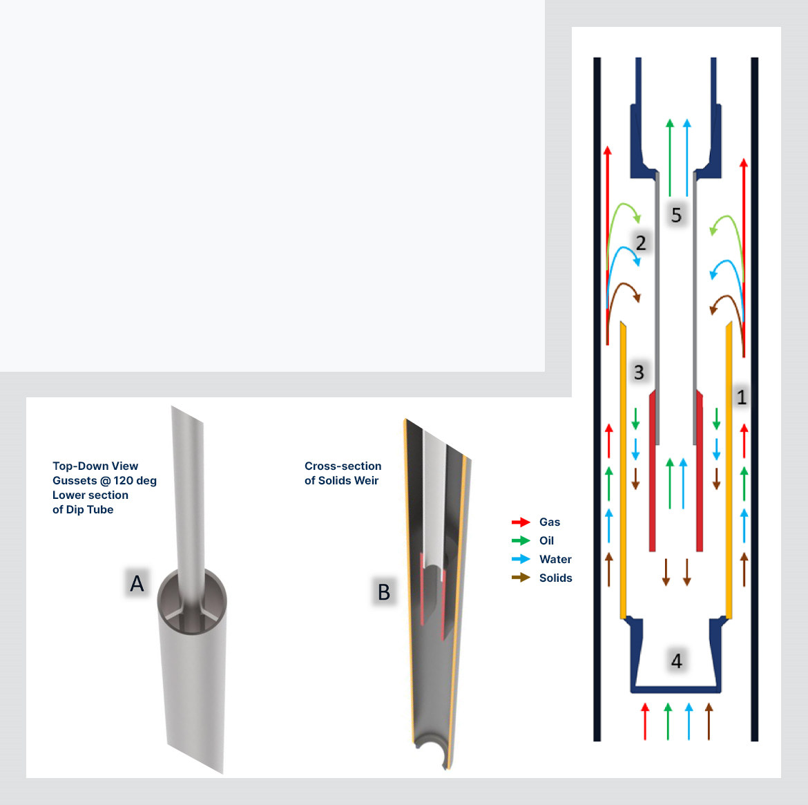
By creating abrupt changes in annular tolerances, the SPRINT Separator creates pressure drops which break out entrained solution gases. This greatly reduces the free gas entry into the rod pump assembly. A ‘Pipe-in-Pipe’ design is simple but effective at separating gas upwards in the casing annulus while dropping solids downward into scalable-length mud-anchor joints placed below the separator.
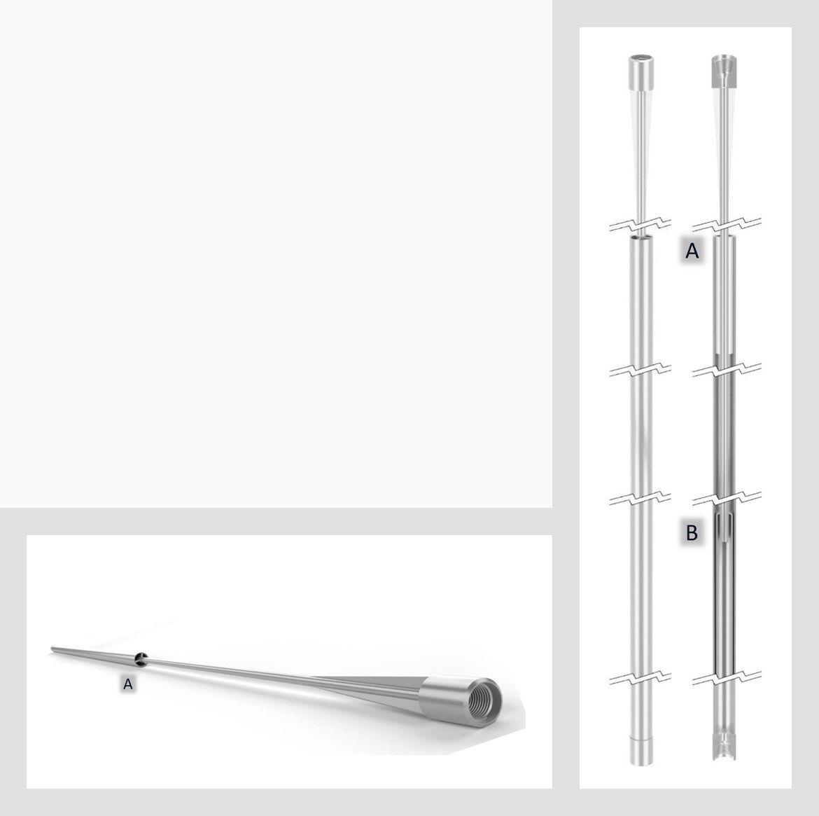
Gussets placed 120° apart on the upper and lower sections of the concentric dip tube provide centralization and increase rigidity for the tool. Additionally, the dip tube sizing increases with tool size to handle greater fluid capacity in higher-volume wells. The 30-foot overall length provides an extended zone for separating gas and solids from the fluid production stream. For harsh wellbores, an optional electroless nickel or Teflon plating offers corrosion protection to extend tool life and reduce interventions.
| Casing OD | Weight | Dip Tube ID | Separator Body OD | Max Fluid Capacity (BFD) | * Fluid Capacity @ 80% Efficiency |
|---|---|---|---|---|---|
| 4.5 | 11.6 | 1.049 | 3.5 | 599 | 479 |
| 5.5 | 15.5 | 1.38 | 4.5 | 913 | 730 |
| 7 | 23 | 1.61 | 5.563 | 1549 | 1239 |
| *Losses of 20% are to compensate for the variation in well fluid velocity from the considered range | |||||
Please enter your name and email address to download Technical Info document.